
GearAndSteel is reader-supported. As an Amazon Associate I earn from qualifying purchases. When you buy through links on our site, we may earn an affiliate commission, at no extra cost to you. Learn more.
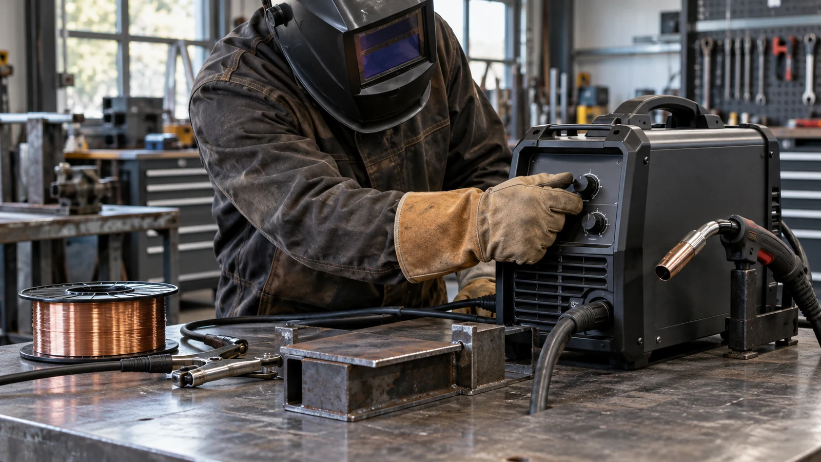
The right MIG welding settings start with your welder’s chart, not a universal voltage number. Match the chart to the metal thickness, wire type and diameter, and shielding gas. Then set wire feed speed and voltage as directed, make a test weld on matching scrap, and change one variable at a time. A chart from a different machine is a reference, not a setting you can safely copy.
MIG settings at a glance: what to check before turning the dials
For ordinary mild-steel welding with solid wire and shielding gas, most constant-voltage MIG machines ask you to establish two core parameters: wire feed speed (WFS) and voltage. Wire feed speed is closely tied to welding current and the rate at which filler enters the puddle. Voltage affects arc length and bead profile. Travel speed, the joint and torch position also change the result, even if the machine settings remain fixed.
| Start with | What it changes | Practical check |
|---|---|---|
| Metal thickness and joint | Required output and joint preparation | Measure the actual part and consider the joint, not just a nominal gauge |
| Process and wire classification | Gas requirements, polarity and usable parameters | Confirm solid GMAW versus self-shielded FCAW on the spool |
| Wire diameter | Usable current range and wire feed setting | Match drive roll, contact tip and machine capability |
| Shielding gas, if required | Arc behavior and protection of the molten pool | Use the specific blend and flow guidance for your procedure |
| Voltage and WFS | Arc stability, bead shape and deposition | Start with the machine chart and tune on scrap |
First decision: if the machine has a chart inside the wire compartment, use the row that matches your setup. If a chart assumes 75% argon/25% CO2, do not reuse the same numbers for 100% CO2 or self-shielded flux-core wire. Miller and Lincoln Electric both treat published settings as starting guidance dependent on the actual setup.
A MIG welding settings chart you can actually interpret
Many charts online present voltage and inches per minute (IPM) as if they were fixed by plate thickness alone. They are not. Miller’s published GMAW parameter method provides a useful rough calculation when no machine chart is available, but it is not a universal recipe. It assumes a suitable solid-wire setup and still requires checking the machine’s allowed ranges, joint, position, and weld quality.
| Mild-steel thickness | Illustrative current estimate from Miller’s rule of thumb | Illustrative wire feed with .030 in solid wire | How to use the numbers |
|---|---|---|---|
| 1/16 in (0.063 in) | About 63 A | About 125 IPM | Planning estimate only; confirm your machine’s chart |
| 1/8 in (0.125 in) | About 125 A | About 250 IPM | Starting estimate; verify voltage and weld behavior on matching scrap |
| 3/16 in (0.188 in) | Do not extrapolate blindly | Use model-specific chart or qualified procedure | Machine output, joint preparation and wire range may rule this out |
Important: these two WFS examples are arithmetic based on Miller’s approximate 1 amp per 0.001 inch and 2 IPM per amp for .030-inch solid wire. They are not measured settings, and the table deliberately provides no generic voltage values. Even a calculated wire speed can be wrong for another machine or transfer mode. The proper voltage must come from the exact welder’s chart or established welding procedure.
To avoid mistaking this for a machine preset, compare the label on your wire, the shielding-gas type and the welder’s own recommended parameter table before attempting a practice bead. A rough current estimate never certifies penetration, strength or suitability for a load-bearing weld.
How to adjust MIG welder settings in a controlled sequence
1. Confirm the setup before energizing the arc
Identify the base metal, thickness and joint. Check the spool classification and diameter, compatible drive roll and tip, work clamp condition, required input power and the welding gun’s condition. Select the correct process and polarity from the specific machine and wire manufacturer instructions. Do not change cable connections inside equipment unless the machine manual explicitly permits that operation; isolate power and refer internal service to qualified personnel.
On standard gas-shielded solid-steel MIG, DCEP (electrode positive) is commonly specified. On Forney 42300 E71T-GS self-shielded .030-inch wire, the manufacturer specifies DCEN and no external gas. The distinction matters more than the similarity of the words “MIG wire” on retail listings. Other flux-cored classifications may differ: always use the exact wire data sheet.
2. Set the machine’s chart values, then make a scrap test
For solid MIG, enter the chart’s wire diameter, material thickness and shielding gas on machines with Auto-Set or synergic controls. On a manual machine, apply the recommended voltage and WFS directly. Use clean practice coupons of the same metal, thickness and joint type, properly secured on a safe work surface, and wear the protection required for arc welding.
Watch the arc, bead toes and material response. A stable sound is useful feedback, but not proof of adequate fusion. If the wire repeatedly drives into the work, the balance between voltage and feed may be wrong. If the wire burns back toward the contact tip, examine voltage/WFS balance, stickout and feed problems rather than simply increasing heat. Follow the machine’s troubleshooting instructions. Adjust one parameter in small steps between practice welds and record what changed.
3. Check the bead, not just the sound
Look for consistent bead width and tie-in without holes, excessive spatter or visible porosity. A tall, narrow bead or poor toe fusion can indicate insufficient energy or travel-speed problems. A wide, overheated bead or burn-through suggests excessive heat input or poor fit-up. None of these clues alone diagnoses the fault, and a good-looking surface cannot confirm penetration or internal soundness.
For brackets, vehicle repairs, pressure-containing parts and structural or safety-critical work, use the applicable procedure and qualified inspection rather than relying on a hobby settings chart.
Solid MIG wire and flux-core need different setup decisions
Settings guides often blur the boundary between GMAW with external shielding gas and FCAW-S with self-generated shielding. The machine may support both, but a settings row does not follow the spool when the process changes.
| Setup | Appropriate use | Important limitation |
|---|---|---|
| ER70S-6 solid steel wire, gas-shielded GMAW | General indoor mild-steel work with an appropriate gas supply | Requires proper shielding gas and machine-compatible wire, tip and spool |
| E71T-GS self-shielded wire, FCAW-S | Outdoor or mobile mild-steel work where gas shielding can be disrupted | Specific wire may be intended mainly for single-pass work; produces slag and fume hazards |
For a smaller shop’s thin mild-steel work: a correctly matched .024-inch ER70S-6 spool, such as Forney 42290 solid MIG wire on Amazon, is a relevant wire option only if your machine accepts the spool size, wire diameter, contact tip and gas setup. It does not fix incorrect gas shielding or a weak electrical connection. It is not an aluminum wire.
For a larger gas-MIG feeder that accepts a 10-pound spool: ARCCAPTAIN ER70S-6 .030-inch solid wire on Amazon is a separate, higher-volume solid-wire option. Do not order it merely because an online settings chart uses .030-inch wire: check spool diameter, weight capacity, feed system, gas and contact-tip size first. A small welder that takes only 2-pound spools is a reason to skip this option.
For an approved self-shielded setup: Forney 42300 .030-inch E71T-GS wire on Amazon offers a different process path, with no external shielding-gas requirement and manufacturer-specified DCEN polarity. Choose it only if your particular welder is rated for FCAW-S and the spool and feed components fit. This is not a drop-in substitute for solid wire on the same MIG chart.
If you already own compatible wire and accessories, there may be nothing to purchase. Fix the settings and test procedure first.
Troubleshooting: which knob should you touch first?
| What you notice | Possible cause | Safe next check |
|---|---|---|
| Wire stubs into the plate | Feed too high relative to voltage, or other feed/technique issue | Recheck chart baseline, WFS/voltage balance and contact-tip condition |
| Wire burns back into the tip | Arc/feed imbalance, excessive stickout variation or feeding fault | Stop and inspect consumable size and feed system per manual |
| Porosity or pinholes | Lost/inadequate shielding, dirty material or gas-system fault | Stop welding; verify process, gas delivery and surface condition |
| Burn-through on thin sheet | Too much heat input, slow travel, wide gaps or inappropriate process | Use manufacturer thin-metal guidance and matching scrap; reconsider joint/process |
| Convex bead and poor tie-in | Insufficient heat, travel-speed or joint-access problem | Review chart, joint fit-up and weld profile before changing one setting |
Do not use voltage adjustment to hide a gas fault. If a bead becomes porous after changing wire or opening the shop door, first check whether the gas-shielded process is still protected. Increasing voltage is not a remedy for a failed hose, incorrect process selection, excessive draft or contaminated base metal. Shut down when troubleshooting requires internal access, cylinder repairs or electrical work outside the operator manual.
Before making a real weld: safety and capability limits
Cover exposed skin, wear a properly selected welding helmet and appropriate gloves and clothing, protect bystanders from the arc, and secure workpieces and cylinders. Remove or control fire hazards, keep suitable firefighting equipment available and follow the applicable hot-work procedure. Welding fumes require assessed ventilation and often source capture; do not assume a doorway fan or a disposable mask is sufficient. Unknown coatings, galvanized parts and stainless steel need material-specific fume precautions. Never weld on closed containers or previously occupied fuel vessels without the required professional cleaning and hot-work controls.
Confirm the welder’s permitted input supply and duty cycle from the exact manual. Do not defeat protection devices, substitute unapproved extension cords or attempt live repairs. If the machine overheats, the circuit protection trips, the work clamp or terminals get unusually hot, or the required safety controls are not available, stop and resolve the cause before continuing.
Bottom line: start with the exact machine chart; treat generic current and IPM figures as estimates; fine-tune one variable at a time on scrap. Buy a different wire only when the actual process, material, diameter and spool compatibility call for it.
Frequently Asked Questions
Should I adjust MIG voltage or wire feed speed first?
First set both from your welder’s recommended chart for the actual material, wire diameter and gas. In conventional constant-voltage MIG, wire feed speed strongly influences welding current, while voltage controls arc length and bead profile. Then make a practice weld and change one setting at a time so the cause of any improvement is clear.
Why does my MIG welder make more spatter after I change wire?
Check whether the new spool uses the same process, classification and diameter. Switching from solid ER70S-6 to E71T-GS may change polarity, shielding requirements, drive-roll choice and usable feed range. Incorrect process setup can create an unstable arc. Consult the exact spool and welder instructions before trying to compensate with voltage.
Can I use a MIG settings calculator instead of the chart on my machine?
A calculator can provide an initial estimate, but it cannot establish the correct voltage, gas behavior, output capacity or joint suitability for every welder. Prefer the manufacturer’s current chart and qualified welding procedure. Confirm the actual result on representative scrap and do not treat visual bead appearance as structural proof.
Do aluminum and stainless steel use the same MIG settings as mild steel?
No. Filler chemistry, shielding gas, wire feed equipment, metal properties and machine features can differ. An ER70S-6 mild-steel row is not an aluminum or stainless-steel welding procedure. Choose the process and consumables using the relevant manufacturer instructions and qualified procedure before selecting settings.